Таблица лидеров


Популярные публикации
Отображает публикации с лучшей репутацией с 10/20/16 во всех приложениях
-
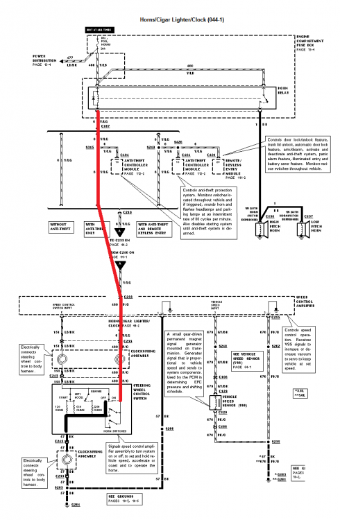
Это феерический успех. Глядя на схему, можно заметить, что кнопка ОН\ОФФ - это "качающийся" двухпозиционный переключатель, который включает либо состояние ОН (в блок круиза подаётся слаботочный плюс через обмотку реле звукового сигнала), либо ОФФ (в блок круиза подаётся минус с массы). Тебе удалось замкнуть оба положения вместе - в результате ты подал массу на обмотку реле сигнала, который и сработал. А вообще гемор ты себе устроил ещё тот. Собрал систему из б.у. железок, работоспособность которых неизвестна. Бери прозвонку и мультиметр, проверяй по схеме сигналы, которые приходят в блок, вакуум проверь, сопротивления в кнопках и там, где указаны на схеме, сигнал от датчика скорости, выключатель стопов и на педали сцепления. На какой скорости ты круиз включал для проверки?
 2 балла
 -
Взбодрим


 2 балла
 -
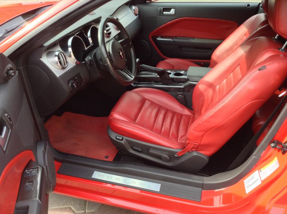
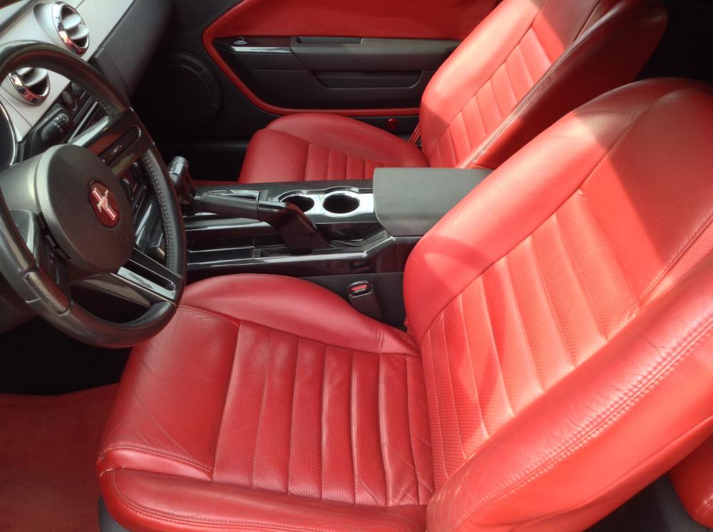
Приходится продать.


 1 балл
 -
Евген, я не ручаюсь за свап в 1995 мотора 4.6, и какой круиз тебе вставили, и какими схемами тебе пользоваться. Принцип монопенисуальный. С небольшими отличиями - убрали вакуум от сервопривода и dump valve, который поменяли на deactivator switch. Остальное тоже самое - лягушки на тормозе и сцеплении, датчик скорости, клокспринг под рулём, мозг, тросик на заслонку Section 10-03: Speed Control System—Electronic 1996 Mustang Workshop Manual DESCRIPTION AND OPERATION Procedure revision date: 05/18/2000 Speed Control System The speed control system consists of: speed control amplifier. speed control cable. vehicle speed sensor (VSS) (9E731). horn relay and bracket (13853). speed control actuator switch (9C888). stoplight switch (13480). deactivator switch (Part of 9F924). clutch pedal position switch (manual transmission only). The system operates independently of engine vacuum; therefore no vacuum lines are required. The speed control amplifier: is mounted on the LH hinge pillar. is connected to the throttle linkage with a speed control cable. integrates system electronics, eliminating the need for any other speed control electronic modules in the vehicle. The speed control actuator switch assembly is mounted in the steering wheel (3600). It consists of: LH buttons (ON, OFF). RH buttons (RESUME, SET ACCEL, COAST). necessary wiring. The vehicle speed sensor (VSS): is mounted to the transmission. is a magnetic pickup driven by a gear which is driven by the transmission. sends a signal to the speed control servo (9C735) proportional to vehicle speed. The air bag sliding contact: is located at the center of steering wheel. transfers electrical signals from the steering column wiring to the following components: driver side air bag module (043B13). horn blow switch (13A875). speed control actuator switch. The stoplight switch: is a normally open switch that closes when the brake pedal (2455) is applied. sends an electrical signal to the speed control servo when closed and disengages speed control system. returns to its open position when the brake pedal is released. Refer to Section 17-01 for additional information. The deactivator switch: is a normally closed switch. replaces the speed control dump valve (9C727) as a redundant safety feature in the system. under normal conditions, when the brake pedal is applied, an electrical (brake on/off) signal from the stoplamp circuit to the speed control amplifier will disengage the system. with brake pedal travel, the deactivator switch will open and remove power to the speed control servo, releasing the throttle from servo control. The clutch pedal position switch is used in parallel with the deactivator switch on vehicles with manual transmissions. Схемы тут на сайте vision-oe FAQ U или сколько и куда лить, крутить. Инструкции, схемы, мануалы. видос по навигации там же. 1996 VacControl 4.6.pdf SpeedControl 1996.pdf Сервопривод так же в левом крыле Section 10-03: Speed Control System—Electronic 1996 Mustang Workshop Manual REMOVAL AND INSTALLATION Procedure revision date: 05/18/2000 Speed Control Servo Removal Disconnect speed control actuator from throttle body (9E926). Raise vehicle on hoist. Refer to Section 00-02. Remove LH front wheel and tire assembly. Refer to Section 04-04. Remove front fender splash shield (16103). Refer to Section 01-02. Disconnect speed control servo electrical connector. Remove two retaining screws from speed control servo bracket (9C736) to fender rail. Remove three screws retaining speed control servo (9C735) to speed control servo bracket. Remove speed control cable cap from speed control servo by pressing cap locking arm and rotating speed control cable cap counterclockwise. Remove speed control cable slug from speed control servo pulley. Gently push actuator cable slug past retaining spring with a small screwdriver. Installation Install speed control servo to speed control servo bracket. Tighten screws to 5.2-7.2 Nm 46-63 (lb-in). Make sure that the rubber seal is snug against speed control actuator cap. Item Part Number Description 1 — Speed Control Cable 2 — Actuator Cable Cap 3 — Seal 4 9C735 Speed Control Servo 5 — Cable Ball Slug 6 — Cap Locking Tabs 7 — Locking Arm NOTE: Incorrect wrapping of speed control actuator cable core around speed control servo pulley may cause a high idle condition. Make sure that the throttle lever is at the idle position after speed control cable installation and adjustment. Install speed control actuator cable slug into speed control pulley slot. Make sure that the slug is fully installed past the retaining spring. Pull on throttle attachment end of speed control actuator cable and draw the speed control actuator cap onto the speed control servo pulley. NOTE: Proper assembly of speed control servo can be verified by a white band on the speed control actuator cable being visible. Install speed control actuator cap by inserting locking tabs into speed control servo slots. Rotate cap clockwise until cap locking arm engages slot on speed control servo. Install speed control cable and speed control servo. Tighten screws to 8-12 Nm (71-106 lb-in). Item Part Number Description 1 9C735 Speed Control Servo 2 — Speed Control Actuator Cap 3 — Screw (2 Req'd) 4 — Speed Control Actuator Cable 5 — Wiring Harness and Connector A — Tighten to 8-12 Nm (71-106 Lb-In) Connect harness connector to speed control servo Install front fender splash shield. Refer to Section 01-02. Install LH front wheel and tire assembly. Refer to Section 04-04. Lower vehicle. Attach speed control actuator to throttle body lever.
 1 балл
 -
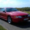
Предстоит не просто забор авты, а целое турне по Матушке России. Вруну привет передавай!1 балл
-
Так эта... Вот же http://challenger-club.ru/ Нет? В межсезоньне через всю Россию - смело! Удачи1 балл
-
Всем привет. Наконец, дошли руки до Доджа, нужно ехать забирать. Собираюсь потихоньку, скоро нужно выдвигаться. План такой: в Новороссийске переобуть на зимнюю резину, посетить по делам Геленджик, далее заехать в Ростов на Дону, там зависнуть на пару дней в клубе по метанию ножей, затем двинуть в Воронеж к родственникам и далее домой в Нижний. Будет и море фото и рассказ и сравнение с Мустангом. Сам весь в нетерпении, жду свободных дней.1 балл
-
DIMAN79 её продавал... Ушатаннейшее состояние.... DEP подтвердит Хотя, не факт... У того еще в салоне пластик был желтым измазан...1 балл
-
Огненный конь хорош)) Думаю, что ковбой для него быстро найдется1 балл
-
А здесь все, как в известном фильме: не будущие, но потенциальные1 балл
-
провоцирует потенциального покупателя! А конь, реально добротный! Удачи в продаже.1 балл
-
Красивый Но название темы прям провоцирует на флуд и торг)))1 балл